
Capacitor Decade Box
Capacitors suck[1], and all of electronics engineering is oriented so that you usually don't have to care too hard what precise value they have. E.g. decoupling capacitors are usually about 0.1–10 μF, and you care more about low ESR than the exact capacitance. Or maybe you're making an RC-filter: you select a capacitor and then vary the resistor over a wide range.
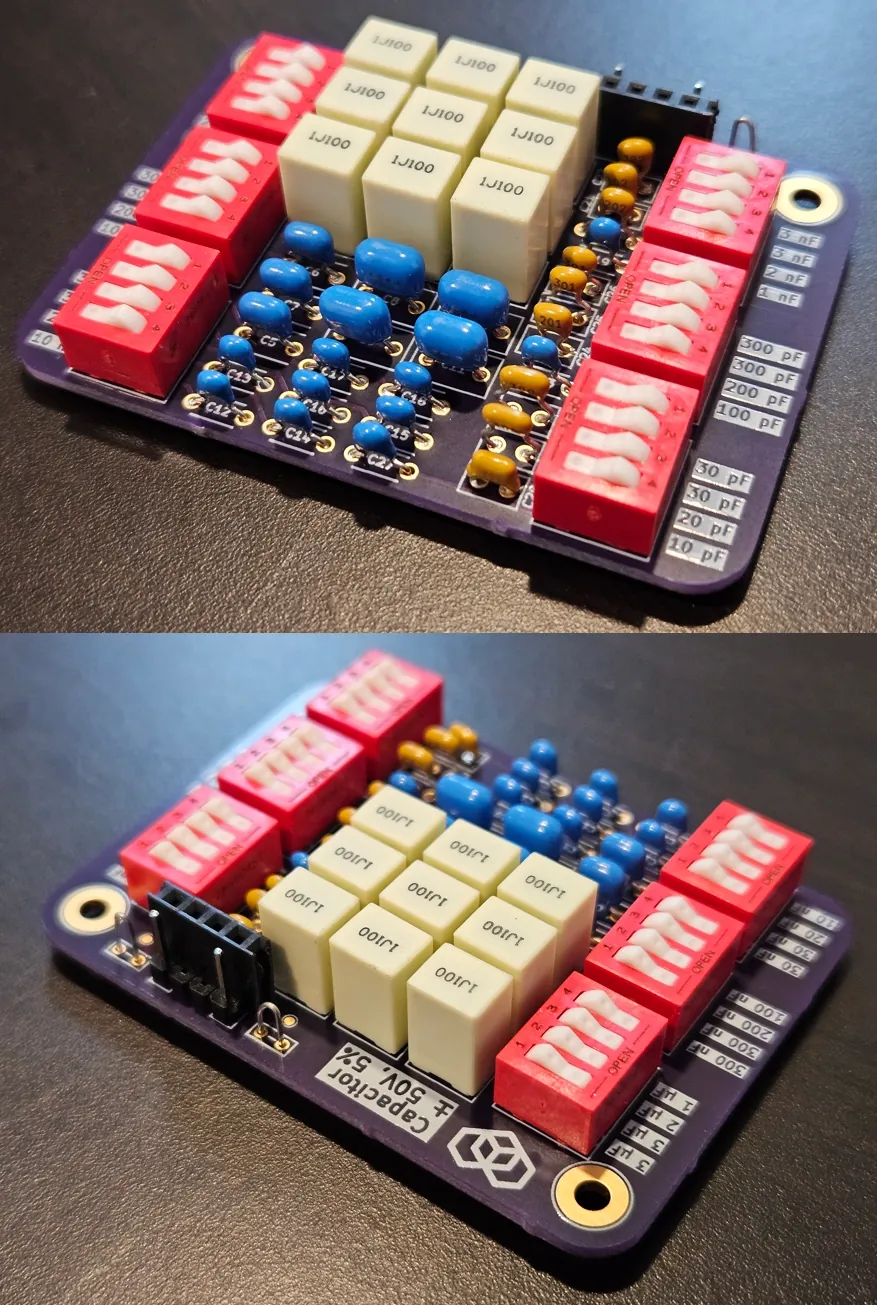
Figure 1
: Two perspective views of the finished capacitor decade box, after assembly.Sometimes, though, you really do want a precisely sized capacitor, but perhaps you're not sure what that particular size is yet[2]. For these cases, we want a variable capacitor to be able to experiment with different capacitances.
Circuit Specification
Unfortunately, because capacitors suck, true variable capacitors only have small capacities (10s of picofarads, perhaps up to 100 pF for very physically large capacitors), so we pretty much need to switch a series of fixed, discrete components instead.
This gives rise to a concept called a "decade box". Instead of varying continuously, a decade box lets you select any discrete value within several decades (powers of ten[3]). Normally, you can choose each digit separately: e.g. select 0–9 in the 1 nanofarads place, 0–9 in the 10 nanofarads place, 0–9 in the 100 nanofarads place, and so on. You can add the circuits to add the values (for capacitors this is just adding them in parallel, so it's particularly easy).
Though they're a bit esoteric, you can just buy decade boxes[4] off the shelf. However, they are bulky and expensive. There are two common products you'll currently see everywhere on the net: IET's stuff (their economy model is as low as $245), and one from McMaster-Carr, with nearly identical specs to the one I ended up creating, for $151.
For DIY use, the only parallel I could find is this $17 thing which operates from 1 nF to 9.999 μF, with 5% accuracy. I considered just getting this, but thought maybe I could do better myself[5].
With all this in mind, we can get an idea of what we want. The following started as goals and were altered somewhat to transform them into the properties of the final device:
- Way cheaper than equivalent commercial decade box
- 5% capacitance error from ≈10 pF to ≈10 μF[6]
- Stable with temperature, time, and DC bias
- Withstand voltage (AC or DC) to ±50V
- Easy to use / select value
- No active switching components like relays or MOSFETs
Circuit Design
Alright, so what approach should we use for making the capacitances?
The simplest and most obvious approach, along with the most intuitive input, would be a decade counter where we set each digit individually, with each digit adding one of 9 circuits. This basically means one capacitor with a value of 1, one with 2, on up to 9. Capacitors don't come in these sizes (they generally come in the E-series, and not even most of it). There is also a lot of duplicated capacitance, which drives up the cost for BoM and any calibration. For example, if the value is 9, we might intuitively expect to use 90% of the capacitance in the decade, but we're actually using only 20% because there are 8 other unused circuits!
On the other end of the spectrum, a binary reduction reduces the space as fast as possible while still being intuitive-ish. This basically means one capacitor with a value of 1, one with 2, one with 4, 8, 16, and so on. However, this is quickly diverges from decades, which does limit the intuition. Worse, it is impossible to source, because the values are off the E-series and become increasingly arbitrary as we get higher. Also, changes often cause large numbers of switches to 'roll over', which is annoying because then you have to do a lot of flipping. From a switching perspective, raw binary seems only practical with automatic switching—which we've already ruled out as disallowed.
Switching capacitors from the E-series itself superficially seems like a good compromise, especially since speccing out an E-series value is likely what the user will be trying to do. However E-series values are not intuitive when we need to add values together. Plus, to achieve a reasonable E6, that's still a fair number of independent circuits.
Returning back to the decade counter approach, good decade boxes don't actually use 9 different circuits. They use binary-coded decimal (BCD), which is only 4 circuits per decade and is still intuitive. Unfortunately, thumbwheel switches outputting BCD are expensive and large, while DIP-switch rotary switches require a tool to turn. None support high voltage. A compromise could be ordinary DIP-switches, set manually in groups of 4 to output BCD. This isn't ideal, but it's the best idea so far.
A big problem with binary in general is that 4 and 8 are not values in the E-series, and therefore parts with those values are difficult to find. Additionally, they are fairly large values within the decade, which makes finding good capacitors more difficult. One can realize 4 as e.g. 3.9 + 0.1 and 8 as 6.8 + 1.2, but it's still not great.
A smarter approach is to use {1,2,3,4} as weights instead of {1,2,4,8}. This can still produce the digits 0–9, although it's not quite as obvious how (see the table below). Everything except the 4 is now on the E-series (and the 4 could be made out of 2+2)!
It is clear we need exactly four weights: there are 9 nonzero digits we need to make, but with three weights there are only 8 possibilities, so nothing we could try could ever work. Meanwhile five or more weights is clearly suboptimal. But perhaps we could use different weights and do better?
Indeed, I quickly found {1,2,2,4} and {1,2,3,3} are also viable sets. The former can be made out of 1s and 2s only (as above, 4 can be made as 2+2), while the latter has all values on the E-series already, resulting in the fewest parts.
Here's a table summarizing weight sets and how they sum to make the digits 1–9; note that in some cases the sums aren't unique:
| Sum | {1,2,4,8} (BCD) | {1,2,3,4} | {1,2,2,4} | {1,2,3,3} |
|---|---|---|---|---|
| 1 | 1 | 1 | 1 | 1 |
| 2 | 2 | 2 | 2 | 2 |
| 3 | 1+2 | 3 | 1+2 | 3 |
| 4 | 4 | 4 | 4 | 1+3 |
| 5 | 1+4 | 1+4 | 1+4 | 2+3 |
| 6 | 2+4 | 2+4 | 2+4 | 3+3 |
| 7 | 1+2+4 | 3+4 | 1+2+4 | 1+3+3 |
| 8 | 8 | 1+3+4 | 2+2+4 | 2+3+3 |
| 9 | 1+8 | 2+3+4 | 1+2+2+4 | 1+2+3+3 |
BCD wastes a lot of capacitance, as discussed. The main advantages of {1,2,3,4} are that it is simple and that it matches the labels on the DIP-switch, but it does still waste some capacitance. Note that {1,2,2,4} and {1,2,3,3} add up to exactly 9, so when we select 9, we actually use 100% of the capacitance available in the decade—these are optimal in that sense!
The latter three choices are all reasonable, and we select {1,2,3,3} somewhat arbitrarily. In the practical circuit, in a few places we actually still have to subdivide the circuit for a weight, but we keep the same weight set {1,2,3,3} from decade to decade for consistency.
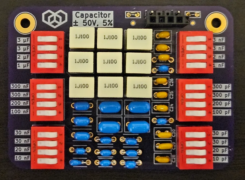
Figure 2
: Top-down view of capacitor decade box. Click to embiggen.Physical Design + Build
Stability and support for AC voltage, along with our requirement for accuracy and stability, would seem to mean C0G ceramic capacitors. Unfortunately, about 47 nF is as high as C0G can reasonably go, and they get pricey. Rather than buy expensive parts or relax my requirements, for the final decade, I used film capacitors instead. These are somewhat more fragile, but otherwise are about as good.
While I was initially shooting for 1% or better accuracy, I decided to relax the requirement to 5%. For example, at the low end 1–10 pF, the most accurate you can get is like ±0.25 pF, which is pathetic (granted, the parasitic capacitance for any capacitor can't go much lower than this, so precision here is kindof pointless). Meanwhile, at the high end, 1% parts become very expensive. Higher precision in the mid-range is quite achievable though (for a bit higher cost).
I went with a small 2-layer board and omitted my usual ground plane (ground is defined externally anyway). To try to minimize parasitic capacitance, I routed the poles mostly on opposite sides of the board, and as directly as possible with the least track. I put header for both male and female wires, testpoints, and bridge testpoints for oscilloscope clips.
I got the boards from OSH Park[7] (not sponsored, just notes on using them for the first time). With the default option, they took 10 days to manufacture these 2-layer boards, but the free shipping was fast. This result was faster but more expensive than overseas economy, while slower and about equal price to overseas expedited. The boards have a beautiful deep-purple soldermask that even exhibited some structural coloration in the sunlight. They didn't bother to deburr the boards, so I had to do that myself (I used sandpaper, with some water, which worked great).
I assembled the boards without trouble and was pleased to find that my design worked as intended. There is about 15 pF of parasitic capacitance, which makes the lowest decade a bit stupid, but other than that I am satisfied.
Wrap-Up
The following project files are provided and can be manufactured freely. (But as always, derivative works should give credit and your support is always welcome.) To download, click the icon:

Finally, yes, I know this capacitor decade box isn't a box. Fortunately, it turns out that being a box doesn't matter. Sometimes you have to think outside the box 😉