Relay Logic: 4-Bit Counter
I picked up 25 or so signal relays for cheap, and was looking around for something to make out of them. I figured it might be an interesting (and limited-scope) project to make a small (4-bit, say) relay-logic register, with an integrated counter.
The final design is fairly simple, but took me a few days to actually build due to debugging of mistakes and tolerance issues. The project itself is built on two of my 'proto-tile' proto-boards, uses 11 relays in total, and treats VCC as 1 and GND as 0.
Relay Experiments
The datasheet situation for this relay (part EA2-5TNJ) is awful. Everyone links a terrible one-page datasheet without even a pinout on it. Worse, there have apparently been multiple breaking design revisions of this part, with the same part number. Here's the better datasheet, for the closest version I could find, branded "NEC", but it contains an error which I'll mention below. Fortunately for me, because I wasn't able to quickly find a useful datasheet, I took the experimental approach.
I soon found that the side with the line on it is the coil. Moreover, I eventually figured out that the coil only works in one direction. This is rather annoying (it rules out an efficient XOR gate, which seems to ultimately cost us an extra relay in the design), and it was not mentioned in the datasheet, which I consider an unforgivable omission.
The relay's nominal voltage is 5 V. The 'set' voltage I measured to be 2.58 V, and the 'release' voltage to be 0.96 V. (This is within spec of 'must set' 3.5 V and 'must release' 0.5 V, respectively.) The coil resistance is nominally 178 Ω, with a tolerance of 10%. Anecdotally, I found a lot of them on the low end[1], though I came up with a nominal of 176 Ω, which is pretty close.
Despite my complaints, these are actually pretty good relays, and I set about making the register part of the counter. Were it not for their single-direction coil and high unit price when new, I would consider using these relays for relay computing, because they are physically small and seem engineered well.
D Flip-Flop Design and Register
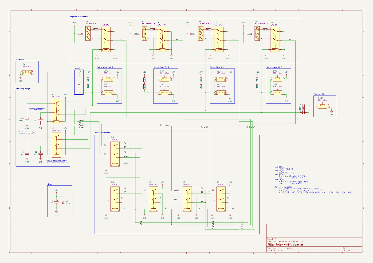
The register is made out of D flip-flops (data flip-flops). It is not at all clear how to make a D flip-flop out of relays, but the best way is to hold the coil voltage in between the set and release voltages, so that if the relay is set, it remains set, and if it is released it remains released. A positive or negative voltage spike from a capacitor (which captures the bit to store; I used several sizes[2] and no charging resistors[3]) will kick over the relay's hysteresis, respectively setting or releasing the relay. (For more on this, see my writeup on memory cells.)
The point right between the measured set and release voltages is 1.77 V, and (with the coil's nominal 178ish Ω resistance as lower resistor) a pullup of about 330 Ω to 5 V forms a voltage divider that holds it there. My big box of resistors, amazingly, didn't have anything very close to 330 Ω, so I made each pullup out of a 30 and a 300 Ω resistor in series[4].

I added 2 buttons for each of the 4 bits, one of which causes a positive voltage spike and one which causes a negative voltage spike (simply as normally open switches that short the coil node to VCC or GND, respectively). I also added another button which does a negative voltage spike on all bits simultaneously, clearing the register (to make that work, one needs diodes out of the nodes, or else this would connect the nodes together, linking the values that can be set into all bits). None of these buttons were strictly necessary, but it makes programming a value into the register very easy, and more fun to play with (as well as easier to test).
I also added RGB LEDs onto the free poles of the register bits' relays: when the bit is 'off', the red cathode is connected through the NC switch to GND on the common pole. When the bit is 'on', the green cathode is connected through the NO switch to GND. I used a 110 Ω resistor on the anode (therefore for both LEDs) and a 40.2 Ω on the red cathode, resulting in the nominal 20 mA current. In retrospect, these LEDs are very bright, and I should have run them much dimmer.
Incrementer
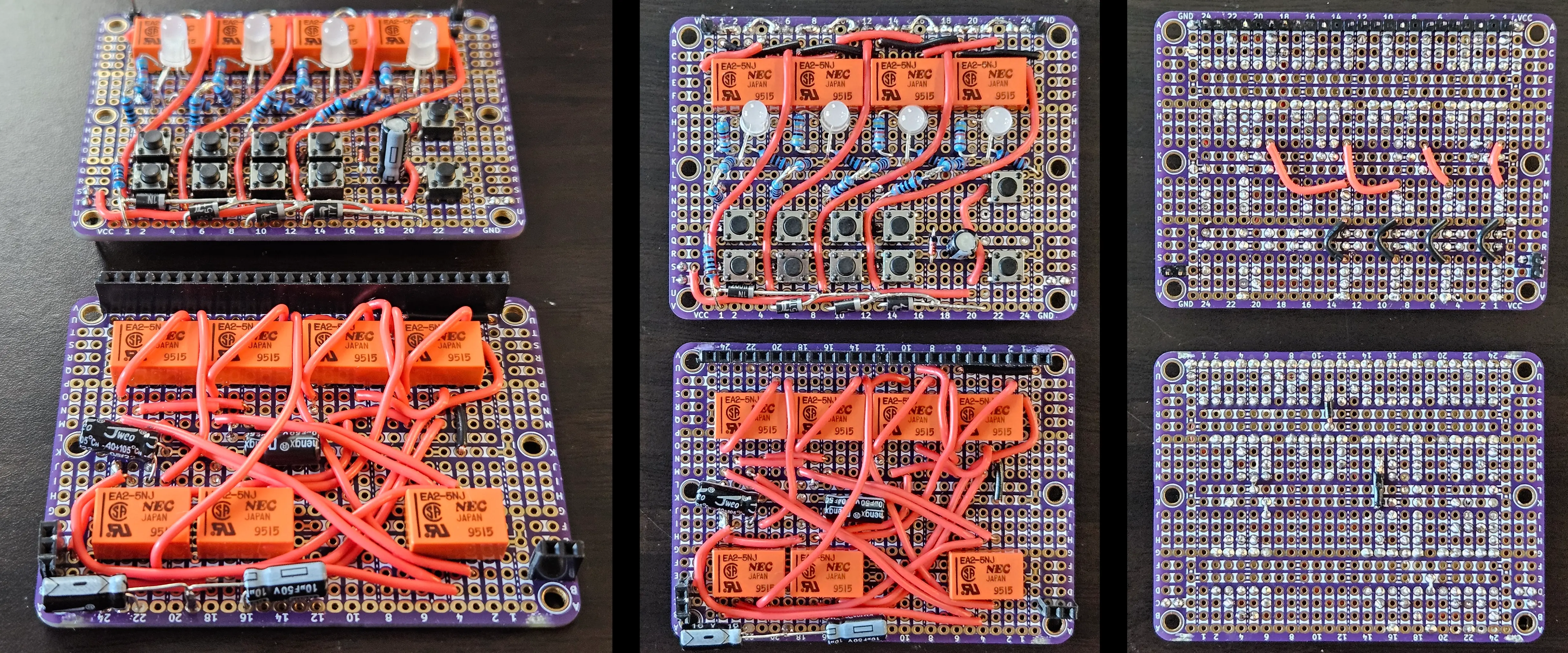
The incrementer is implemented on the lower proto-board, connected to the upper by header. Not all pins in the top row[5] of header are populated. Ground comes through the top and lower-right headers, while power comes through the lower-left header. The lower-left header also carries the increment signal from a button on the top proto-board.
The incrementer basically reads whatever value is in the register and adds 1 to it (with rollover). I developed this circuit for Mr. Clicky-Clack from scratch to minimize relay count (albeit probably while retaining a constant-time increment; this architecture increments n bits in a fixed gate-delay of 2). I tried to optimize it down from 5 relays (as above, I think it could have been 4 if a bidirectional coil enabled an efficient XOR gate). The circuit is best understood by looking at the circuit diagram below.
The incremented value is passed through the two relays at the bottom-left of the lower proto-board and stored into sampling capacitors. When the increment button is pressed, the relays flip, connecting those capacitors to the coil nodes of the register, causing positive or negative voltage spikes and setting the bits appropriately. These sampling relays would normally be designed to flip as a 'release' instead of a 'set', because the former is faster for most relays, but the difference is a matter of milliseconds and it was easier in this case to assemble the circuit as a 'set': the increment button connects both negative coil pins to ground.
Wiring all this was tedious and messy but ultimately straightforward.
Click to embiggen:
Circuit Diagram and Misc.
I added a decoupling capacitor (10 μF) across the power rails, as well as a Zener diode as simple voltage protection (it is not built to be a proper TVS diode, so this is really just wishful thinking). Some header for VCC and GND posts completes the build. I gave the finished thing to a friend.
Click to embiggen: