CS 6620.001 "Ray Tracing for Graphics" Fall 2014
Welcome to my ray tracing site for the course CS 6620.001, being taught at the University of Utah in Fall 2014 by Cem Yuksel.
Welcome fellow students! I have lots of experience tracing rays, and with graphics in general, and so I'll be pleased to help by giving constructive tips throughout (and I'll also try very hard to get the correct image, or say why particular images are correct as opposed to others). If you shoot me an email with a link to your project, I'm pretty good at guessing what the issues in raytracers are from looking at wrong images.
Hardware specifications, see bottom of page.
Timing information will look like "(#t #s ##:##:##)" and corresponds to the number of threads used, the number of samples (per pixel, per light, possibly explained in context), and the timing information rounded to the nearest second.
Project 4 - "Reflections, and Refractions"
Well, I did it again: I ripped apart my materials code and rewrote a lot of it. My last redesign got a lot of things right, but it wasn't perfect. This redesign still isn't perfect, but I think it's a major improvement yet again.
The main thing that's lacking is support for multilayer materials and tabular BSDFs. Adding these will take some work, and I think it was a mistake to try adding them so soon.
The solution to my architectural woes turned out to be a quite deep inheritance hierarchy (I wanted to say "mother of all inheritance hierarchies", and then I realized that that overloads the "parent"/"child" terminology that inheritance is already using—so you'd get only one inheritance hierarchy, heh). This is quite possibly the deepest inheritance hierarchy (and one of the largest) I've ever used in production code. Materials have a std::vector of Layers. Each Layer has a BRDF_Base BRDF, BTDF_Base BTDF, and EDF_Base emission distribution function (EDF). The hierarchy for those is (bold is currently implemented):
- DF_Base
- BSDF_Base
- BRDF_Base
- BRDF_DiffuseBase
- BRDF_Lambert
- BRDF_OrenNayer
- BRDF_SpecularBase
- BRDF_IdealMirror
- BRDF_Phong
- BRDF_BlinnPhong
- BRDF_AshikhminShirley
- BRDF_CookTorrance
- BRDF_GTR
- BRDF_GGX
- BRDF_HTSG
- BRDF_Lafortune
- BRDF_RawData
- BRDF_TorranceSparrow
- BRDF_Ward
- BRDF_Composite
- BRDF_ThinFilm
- BRDF_DiffuseBase
- BTDF_Base
- BTDF_IdealDielectric
- BTDF_RawData
- BTDF_Phong
- BRDF_Base
- EDF_Base
- EDF_Lambert
- BSDF_Base
With the exception of maybe EDF_Base and BRDF_DiffuseBase, none of these layers are unnecessary. The work of computing these distribution functions is delegated across all of these layers in one way or another. Most of the lower-level classes implement just the functions without taking into account color scaling, Fresnel, alpha, and so on. There are a lot of virtual methods.
I'm mostly happy with the way this is structured. There will probably be a few changes, but mostly it will stay this way from now on. I hope.
One of the nice features about doing all this is that it lets me represent a huge variety of materials quite accurately. For the given images, for example, the material needs to be non-physical. This is implemented with BRDF_Composite combining BRDFs BRDF_Lambert, BRDF_BlinnPhong, BRDF_IdealMirror, and BTDF_IdealDielectric as necessary.
An important consequence is that my tracer supports images with nested indices of refraction (in the given images, the rays are actually "inside" an air material, which has an IOR of \(1.000277\)). Attenuation is also computed for all rays, although air varies too much to justify having a nonzero default.
At this point I'm going to have to say it: I'm breaking conformity with the expected images. It's just too difficult/degrading to try to work in these nonphysical things. For example, from what I understood in class, the given images are supposed to be rendered with diffuse, specular, a delta transmission and a delta reflection—all at the same time? That doesn't even make sense! I worked it in nevertheless (in an additive sortof manner, which is the only half-sane way to even try implementing such a ludicrous BSDF), but I can't render it using a Whitted renderer because my system treats all BSDFs equally (I can't send a refraction ray and a reflection ray and sample the lights, but only do so for particular materials). I probably could fix that, but at some point I've got to draw the line at crufting a workaround to make something that doesn't make sense work.
So, my Whitted renderer instead chooses an importance sampled ray that either reflects perfectly or refracts perfectly. This is the only way it is allowed to recurse. As for loading, Fresnel is disabled on all materials' layers, except if the layer contains a refractive BTDF. It's wrong wrong wrong wrong wrong, but that's how it is. I may consider breaking further in future projects and just using my tracer in all its physically accurate glory.
Without further ado, here's the test image, sans diffuse and specular cruft on the spheres (16t 100s 00:11:42):
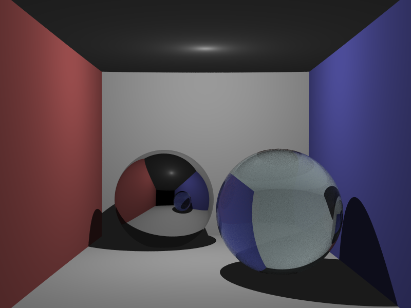
It looks quite different (and the high-variance Fresnel makes it look worse). Oh well—at least it's not wrong. Well, it has the ambient light, I guess . . .
Well that's depressing. On to better things. Like:
It's time to resurrect my path tracing backends! Woohoo! I made this part a while ago, and now I think it's time to share. The box scene I immediately recognized as the variant of the Cornell Box by SmallPT. My renderer can't handle the walls being the insides of the spheres (it means air has a higher priority, and so they need to have negative priorities; this means that refraction out/intersection is meaningless for anything except one of the walls), so I worked out that the thing best approximates an axis-aligned box starting at \(\vecinline{1,0,0}\) and going to \(\vecinline{99,81.6,170}\), with camera position / center / up being \(\vecinline{50,52,295.6}\) / \(\vecinline{50,51.957388,294.6}\) / \(\vecinline{0,1,0}\), an image plane of \(1.0\), and a vertical sensor size of \(0.5135\). I represented the walls and floor with triangles, but I made the ceiling a plane (otherwise the large spherical light leaks around the front, I think). Let's render it (16t 100s 00:11:02):
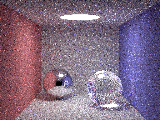
. . . oops.
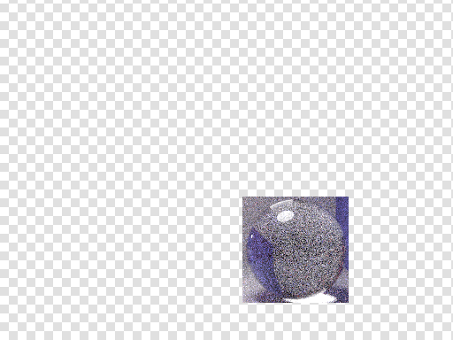
I spent an embarrassingly long time on this one—although perhaps not, considering it was a subtle problem. The problem was that the importance sampling method for choosing reflection versus refraction rays was broken. I was selecting the reflection direction according to the reflection, but I was then setting the PDF for the entire ray to be that reflection. In actuality, this isn't importance sampling at all! Well, it kindof is, but not that way. I changed it to a simpler 50/50 PDF; then it made this image of just the refractive sphere (16t 1000s 00:04:55) (and a double resolution version, shrunk; view original to resize; (16t 1000s 00:20:10)):
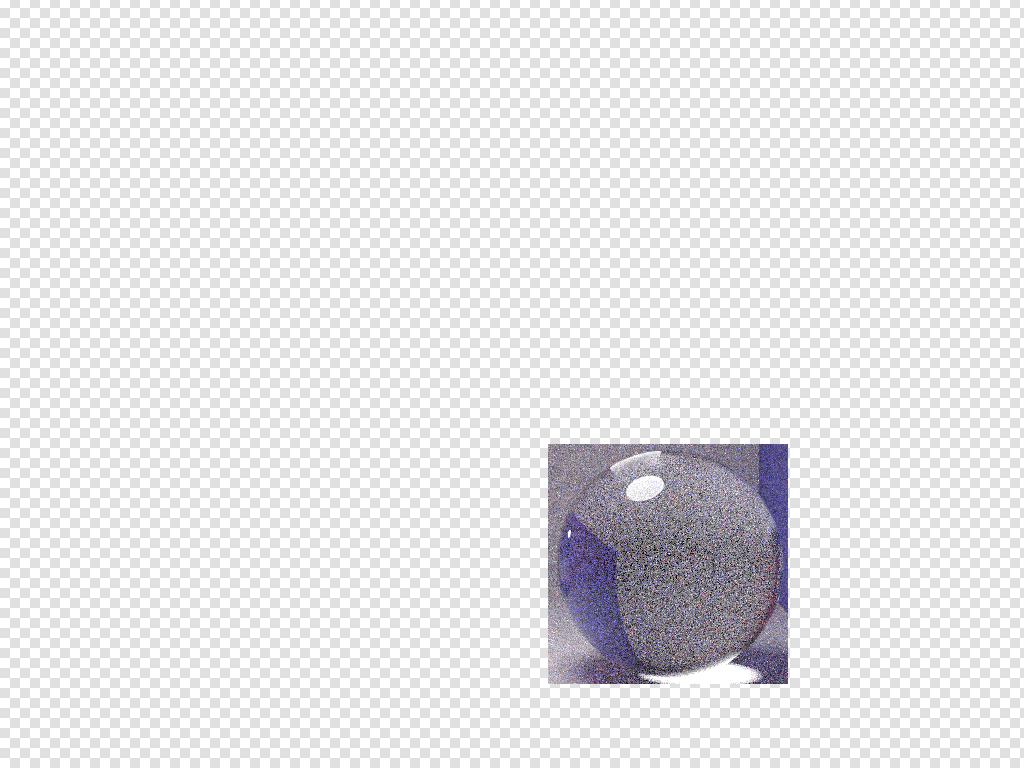
Well, a 50/50 PDF is pretty lame if you have a tiny chance of reflecting. I fixed the sampling (the PDF should be \(1\)), but you still choose reflection versus refraction according to the Fresnel coefficients. The first test image (16t 1000s 00:02:33):
I was going to have my tracer render the larger version, but I decided that would be a pointless exercise. Instead, it's time to render something new.
(16t 500s 05:43:30), maximum ray depth \(8\):

The Stanford Lucy model is \(~28{,}055{,}742\) triangles. While trying to open it, Blender nearly crashed my computer by running it out of memory (my computer, remember, has 12GB of RAM). It also took me a while to find the mesh: the model is also spatially large; I scaled it by \(0.01\), and that made it at least fit on Blender's grid. I figured that \(28\) million polys was still too much, but when I tried Blender's decimate, it gobbled down so much memory so quickly that I had to hard reset. Meshlab is much better for this task. It, reasonably quickly, and without touching my memory bound (it looked like it was respectfully keeping its distance), decimated the mesh to \(10\%\), \(1\%\), \(0.1\%\), and \(0.01\%\). My renderer could probably handle the larger versions, but most of that detail is superfluous (the render above is \(1\%\)).
Since this was such a long render, I had my tracer save its progress. It dumped \(12{,}288\) files (together \(18{,}874{,}368\) bytes) comprising chunked HDR image data in a temporary directory.
Another thing that's striking is how much the maximum ray depth affects render time. You're not supposed to stop rays; theoretically a ray could bounce forever. So you use Russian Roulette to kill the rays. The way it works is you kill each ray with a certain probability each bounce (say, one minus the reflection coefficient). Thus, the ray will always stop after some point, but it is a theoretical unbiased estimator for the entire space of infinitely many reflections. Setting a maximum depth adds bias, and is technically wrong. The images for this project used up to eight bounces. For diffuse interreflection, this is often plenty.
The above image was rendered using naïve path tracing—which means the ray bounces around until it just happens to hit the light. Clearly, this is inefficient. The Whitted ray tracer was getting results in seconds for similar scenes that were much better looking in many ways (there wasn't any radiosity, but there was very little variance).
The common solution is to use explicit light sampling, where at each step you send a ray toward the light source directly. The problem with this is that for certain kinds of objects (e.g. perfect specular surfaces) the chance of that light ray being along the perfect specular direction is literally \(0\). One consequence is that caustics from perfect specular surfaces are not sampled at all.
This has been a longstanding issue for my tracer, but it can be corrected by treating delta function surfaces individually. I hadn't done this before because my tracer was really only originally built to handle real BRDFs (which aren't delta functions). It's a surprisingly easy modification to try to do (although you need to be a little careful to get it right). Here's Lucy again, with just \(15\) samples per pixel (16t 15s 00:04:38):
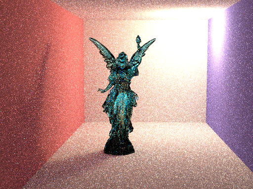
The above is of maybe half the quality of the naïve path tracer (and it's half the resolution), but it shows that the concept works. There's also a problem in the implementation, which has been fixed here (16t 64s 01:20:32):
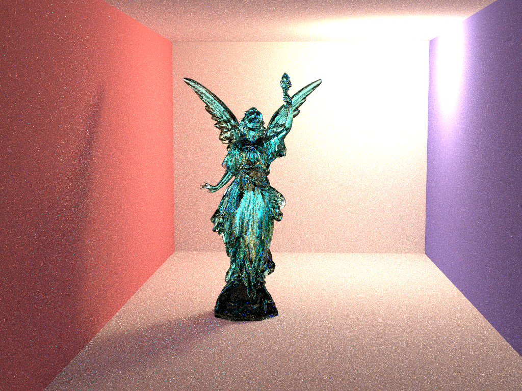
Of course, the point of this scene was to have pretty pretty caustics. Part of the problem is the light; it's too large. The other problem is undersampling (See those bright cyan flecks in the shadow? Those are supposed to be largely smoothly-varying refracted light). Although my explicit light sampling code helps, this is really a job for bidirectional path tracing or photon mapping—so that snazzy image will just have to wait a little more.
Proceed to the Previous Project or Next Project.
Hardware
Except as mentioned, renders are done on my laptop, which has:
- Intel i7-990X (12M Cache, [3.4{6|7},3.73 GHz], 6 cores, 12 threads)
- 12 GB RAM (DDR3 1333MHz Triple Channel)
- NVIDIA GeForce GTX 580M
- 750GB HDD (7200RPM, Serial-ATA II 300, 16MB Cache)
- Windows 7 x86-64 Professional (although all code compiles/runs on Linux)