Making a Hex Display: Part 1
Parts in this series:
Part 1: Motivation and Research
(this page)Part 2: DIY Prototype
Part 3: Six-Teeny Display and Programmer
While building my relay computer, Mr. Clicky-Clack, I got the idea to visualize the stored value of each register, not as binary but as hexadecimal.
Hexadecimal is a more compact way to represent numbers[1], and certainly less unwieldy for humans than binary. However, it is still in perfect correspondence with binary, in that exactly four binary bits equals one hex digit[2]. So, the game is, you have four input lines, and you need to draw the character '0', '1', '2', '3', '4', '5', '6', '7', '8', '9', 'A', 'B', 'C', 'D', 'E', or 'F', according to its value (or using '0'–'9' and 'a'–'f', lowercase, is also fine, and perhaps better[4]).
Off-the-Shelf Segment Displays
The obvious and common way to do this is with a cheap 7-/8-segment display (Figure 1). However, we quickly realize a problem. If we choose uppercase, then 'A', 'C', 'E', and 'F' are fine, but 'B' looks identical to '8' and 'D' looks identical to '0'. If we choose lowercase, then 'c' and 'd' are fine, but 'a' looks weird, 'b' might be confused with '6', and 'e' and 'f' are impossible (an 'e' that is as tall as an 'E' is possible, but that's bogus and doesn't count).
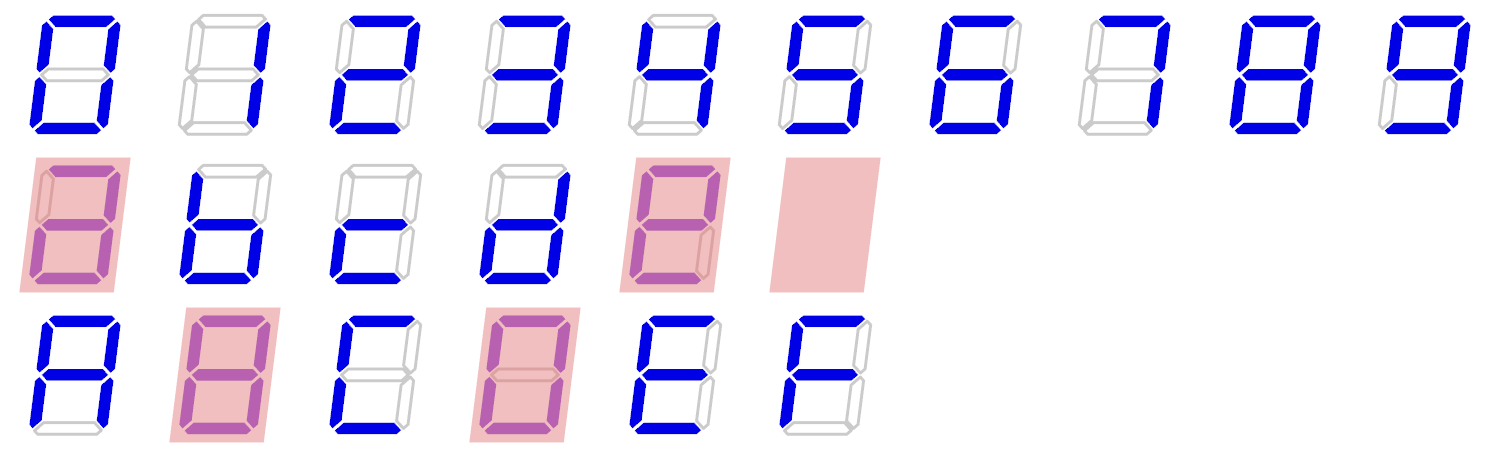
Figure 1
: Possible hex digit glyphs on a 7-/8-segment display. No lowercase 'f' is possible, and some glyphs are ambiguous or wonky (red highlights). (Image by me.)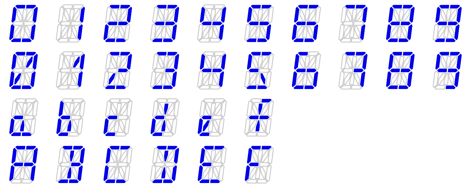
Figure 2
: Possible hex digit glyphs on a 16-/17-segment display. Some minor ambiguity persists, but this is probably today's best solution. (Image by me.)People will gleefully pose non-solutions, such as just ignoring the problem and inferring the result from context or an added radix point.
The commonest approach, though, is just to use mixed case, something like 'A', 'b', 'C'/'c', 'd', 'E', 'F'. The lowercase 'b' is still a little ambiguous with '6', but it's overall pretty okay ambiguity-wise. The (now-defunct) DM9368 decoder/driver was designed for exactly this, and a microcontroller seems to be the best solution today. However, the problem is you're now mixing case! This will instantly annoy any real programmer, and is obviously unacceptable.
We can alternately just use a 16-/17-segment display (Figure 2). The glyphs for '0', '1', '3', '5', and perhaps '2', '6', '7', and '9', can be improved (or at least, adjusted[5]), but the real attraction is the letters. Lowercase and uppercase both look reasonable, though the situation is not optimal. '8' might cause confusion with 'B' if you didn't know a-priori that 'B' has these imitation serifs; this is at least avoided for '0' vs. 'D', by giving '0' a slash and 'D' the serifs, distinguishing each from the other. Lowercase 'a' has quite a bit of a tail, and all lowercase letters except 'f' are not centered.
On the whole, though, a 16-/17-segment display is the normal 'good' solution, with lowercase probably being overall best[1]. You do need a complicated driver circuit for it, though, since decoding a 4-bit signal into the appropriate LEDs is nontrivial.
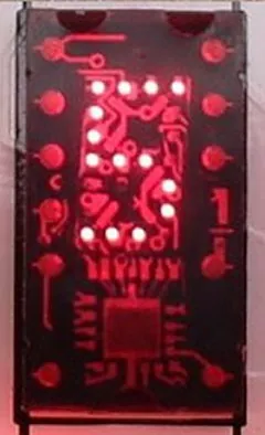
Figure 3
: The TIL311, the now-defunct part which inspired the project. (Crop from image source.)Obsolete and Hobbyist Hex Displays
The professional turnkey solution for hexadecimal[6] at one time actually existed. TAOS (Texas Advanced Optoelectronic Solutions, a spinoff from Texas Instruments) produced for a long time the TIL311 (Figure 3) (and variant DIS1417[7]), apparently licensing the TI design. The TIL311 basically does exactly what we want: it has 20+2 LEDs (the extra two are for a left and right decimal point) arranged in an unusual pattern (Figure 4) that allows for clear (uppercase) glyphs. You pipe in four bits for the data and the right character shows up. You can even use PWM on a dedicated "blanking" pin to change the brightness. All functions of the chip can be controlled with a convenient 8 bits.
The TIL311 became iconic in older electronics[8]. So beloved was the TIL311, it inspired HP to clone it (the HTIL-311A) as well as to make their own (the HP 5082-7340 and derivatives HP 5082-7359 and HP 5082-7306). Today, all of these displays are valued for their vintage look, even when only displaying decimal data.
The TIL311 was (as were other displays of the time) based on older technology, requiring 5 volts[9] and a high current[10], and the LEDs having a short lifetime. The final nail in the proverbial coffin is that TAOS was eaten in 2011–2012, and the TIL311 stopped being manufactured. Although there is a lot of new-old-stock and old junk-drawer boards containing TIL311 chips, scarcity is inevitably driving the price up, to where today just a single TIL311 will set you back about $30[11], which is far too much for just plonking a gazillion of them into your circuit. The TIL311 alternatives are even more expensive, and none of these are an ideal solution anyway owing to the higher voltage and short lifespan.
Faced with this problem, a few hobbyists have tried to recreate their own. The PICTIL (also on OSH Park) mounts many components on the back for a clean look. They improved the design and did tests with resin packaging in a revision, the reTIL (see also). The other project is the DIYTIL311, which appears to have been abandoned in the fabrication stage. None of these are commercial ventures.

Figure 4
: Infamous diagram extracted from the TIL311 datasheet, showing the LED glyph patterns. Notice that each glyph is unambiguous.Doing it Myself
So, we're stuck. The professional solutions are dead, the parts expensive and getting rarer. The hobbyist solutions are toys, not production. I had never done automated PCB assembly before, so I figured I'd give it a go.
I quickly established some design goals:
- Decode 4-bit input into a hexadecimal character using the same iconic LED arrangement as the TIL311.
- Be cheap to mass-produce, and use current parts.
- Support a variety of colors.
- Accept a wide range of voltage, and at least 3.0–5.5 V (to accommodate 3.3 and 5 V logic).
- Be a similar form factor to a standard 7-segment display.
In particular, it was not a priority to match the pinout of the TIL311, because I thought I could do better. I can see a left decimal point being useful, but to get the spacing between digits right, you really only want one on the right, and modern displays have standardized on this. Also, the latching mechanism doesn't seem very necessary to me. Finally, the blanking input is mainly only useful for PWM, but this places some demand on the host microcontroller, especially if you want to be gamma-correct: it's more user-friendly to have an analog input.
In the next section, I'll dive into the actual build!
Back to Six-Teeny Intro or Electronics Projects.