Making a Hex Display: Part 3
Parts in this series:
Part 1: Motivation and Research
Part 2: DIY Prototype
Part 3: Six-Teeny Display and Programmer
(this page)
The prototype board I invented (in part 2) was working, but there was lot of room for improvement. This chapter mostly discusses the upgrades I made to it, to make it a board I call the 'Six-Teeny'[1].
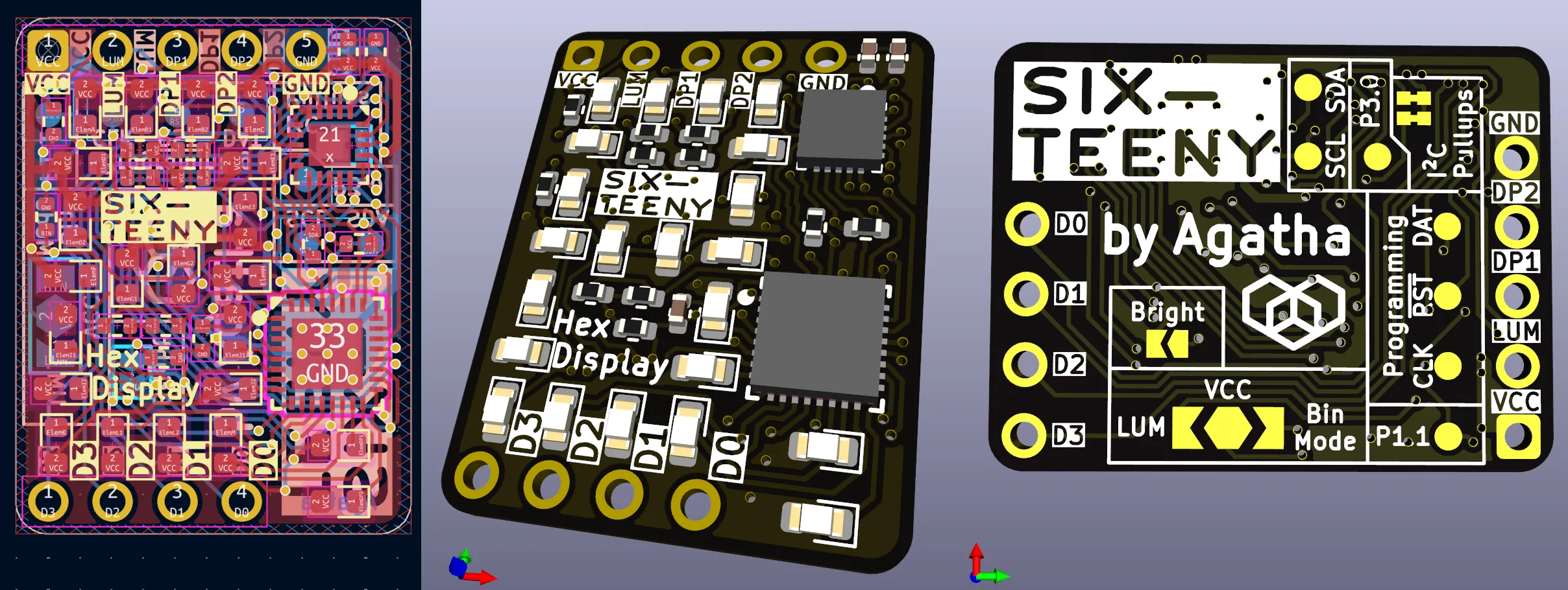
Figure 1
: The hexadecimal display, called the 'Six-Teeny', developed in this chapter, rendered in KiCad.BIN Resistor and Jumper
I had intended to use the microcontroller's internal pulldown resistor for the BIN pin, but while writing the code, I realized I had skimmed the datasheet incorrectly and it doesn't actually have one. For this reason, it is disabled in the code on the prototype boards. I fixed the problem by adding a discrete pulldown.
I also increased the size of the LUM ← VCC → BIN jumper and moved it to the back side to make it more accessible. I didn't place it there initially because I worried that the exposed copper could lead to unintended contact with an application circuit and/or applied solder thickness messing with the seating of the part. However, on the top the jumper is too close to the LEDs to easily solder, and would be completely inaccessible if packaged with resin (as in the TIL311). The issues of shorting and seating also seemed, on reflection, to be slightly far-fetched, so I think moving stuff to the back side is a good idea on balance.
Pogo-Pins
Programming the prototype boards was challenging because of the ad-hoc position of the programming pins on the top of the board. I did it that way because the alternative was to place it on the bottom of the board. It wouldn't be accessible to breadboarding, yet as above, I was worried it could cause shorting.
I had heard of pogo-pins, but all the ones from normal suppliers were on the order of dollars per pin, which I felt was excessive, and I had felt like keeping it simple for the first prototype. The consequence was you had to program it with a fiddly improvised probe made out of some old leads and header[2] that is a pain to get set up on the pads, especially if you don't want to solder to the THT pins either.
The working prototype now in hand, and the issue of electrical shorting to a hypothetical application resolved as far-fetched, I set about to solve the connectivity problem with a proper pogo-pin jig. The standard pogo-pins to use for these jigs seem to be the sketchy "P75" series, which I take to be so widely counterfeited that no one knows who (if anyone) actually makes the originals anymore. No company appears on the vintage chinglish datasheet JPEG. I bought 100 each of the cone-tipped P75-E2 and flat-topped P75-G1 for a far more reasonable price.
I was able, with some difficulty, to place pogo-pin pads on the underside of the board for the three programming pins. I deliberately moved them to be horizontally between VCC and GND, so one could theoretically make a DIY pogo-pin rig by jamming five pogo pins horizontally into a breadboard[3].
Exposed I2C Bus and GPIO
The I2C bus is used for all of 5 millimeters between the MCU and driver, but given how useful hacking it was for my ad-hoc debugging (in the previous chapter), I decided to expose it with more pogo-pins. It dawned on me that this would turn the board into a true platform, capable of orchestrating multiple devices and really making the "programmable" nature of the device felt. It was in turning it into a platform that I gave the board its name, the "Six-Teeny".
I foresaw that multiple devices might be connected to the I2C bus, and they might or might not have pullup resistors. For example, connecting four displays up and controlling them all from a Pico would put four 4700 Ω resistors on each line in parallel (so 1175 Ω total[4])—too small a pullup resistance! Therefore, I also added a separate jumper for each resistor (note that a single jumper would not be acceptable[5]).
I also routed the address lines of the driver (previously connected to VCC, as that was easiest) to some free GPIO pins on the MCU. This allows the driver's I2C address to be set from MCU logic. In our example with four boards, the host MCU could connect with each board's MCU and tell it to reset its LED driver and give it a particular I2C address. Then the host MCU could drive the displays itself.
But how would the host MCU connect to the boards' MCUs? Well, there's the newly exposed I2C bus, of course, but all the boards' MCUs will themselves boot with the same I2C address. For further flexibility, I realized I should try to break out the two remaining free GPIO pins. With a huge amount of effort, I was able to successfully route these to yet two more new pogo-pin pads!
Firmware Color Correction and Brightness Jumper
It's not clear from the LP5024 LED driver datasheet, but the way it works is each LED gets an 8-bit brightness, and there is an overall 8-bit brightness it gets multiplied by. The 16-bit result is downsampled to 12 bits, and then that drives a 9-bit PWM signal, with an additional 3-bit temporal dithering scheme to get effectively 12-bit precision.
For simplicity, I had used an 8-bit brightness, leaving the factor at 255 and logarithmic PWM correction (a handy feature provided by the driver) enabled. However, at low brightness I was getting artifacts and the N76E003 microcontroller has a 12-bit ADC, which seems too perfect for mapping onto a 12-bit output to pass up.
To improve the firmware, I changed the PWM response to linear, and generated a table of 4096 pairs of 8-bit numbers, where the first number is the LED brightness and the second is the factor. The table is constructed so that when multiplied and converted to 12 bits in the driver, the result is as close as possible to the logarithmically corrected PWM rate. The linear brightness from the ADC is of course used to index into it.
I had a bit of trouble with SDCC hanging, trying to pack the whole 8kiB table into RAM (which is far more than the 1kiB the MCU has), but there's plenty of flash space. The latency likely takes a big hit, but "big" here is relative—we're talking 10s of microseconds, probably. Even copying the data over the 400 kHz I2C bus will be 770 μs, and human perception won't notice for 1000s–10000s of μs.
Brightness Resistor / Jumper
Even with the 12-bit precision, at low brightness there was not great precision. Mainly this is because of the logarithmic brightness curve that's required to make the brightness be perceptually linear. That's slightly problematic since the 20 LEDs, each at about 20 mA, are very bright, and they need to be dimmed a lot.
To solve this, I added another resistor in series to the reference pin the LED driver uses to configure the LED current, thus decreasing the nominal current from ≈19.3 mA to ≈1.44 mA. That's a big reduction, but it works out perceptually, again because of the nonlinear human visual system. I find about 1.1 mA right, so 1.44 mA gives room to adjust up or down to suit.
However, I still wanted access to the full brightness, so I also added a jumper that shorts across it, restoring the original range (at the lower precision), if for some reason you want all that eye-searing brightness back.
Misc. Improvements
- One of the first things I noticed was that the D0–D3 labels on the back silkscreen were backward. I don't know how—I checked it countless times—but the mistake was mine. Easily fixed.
- Applied missing soldermask under the microcontroller and on the thermal vias under the LED driver.
- As mentioned, I named the board the "Six-Teeny": a pun on "sixteen" emphasizing the small but still capable platform.
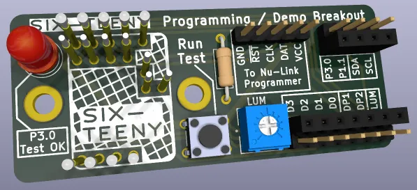
Figure 2
: Programming board for the Six-Teeny in KiCad.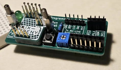
Figure 3
: Programming board for the Six-Teeny, assembled!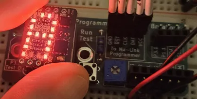
Figure 4
: After programming the Six-Teeny, the programming board can be used as a demo board. Here, 10002 is being piped in at the bottom right, and the Six-Teeny is correctly displaying 'A'.Programmer / Demo Breakout Board
I decided to just design a breakout board for the display, since even with the pogo pins (and even them being arranged for breadboarding, at that), I wanted a solution that could connect to all pins, and was quite frankly neater and more permanent.
The basic breakout board was trivial in comparison to the routing nightmare of the Six-Teeny itself, though I quickly made it less trivial. I added M3 mounting holes so you could plop down a spacer and make a clamp to hold the board[6]. I made the board a little bigger so that the bottom of the rightmost bolt would not conflict with the breakout pins on a breadboard. This left quite a bit of empty space.
Since NatureAgatha abhors a vacuum, I put an LED and a resistor in. Somewhat inspired by the notion of a testing board, where you push a button and it runs through a test, I added a little push-button in the form of those tactile switches that never seem to sit comfortably in breadboards and have a weird double internal connection[7]. I connected the switch to the newly broken out GPIO P1.1, which has a pulldown, and the LED to the other one, GPIO P3.0. The idea is that the LED starts unlit (on boot, the MCU sets most pins as high impedance inputs), but then when you raise P1.1 with the button, the board cycles through its characters and sets P3.0 high. The GPIOs wouldn't connect to anything unless you've got programming access, so this testing feature can simply be built into the default software for every board! Finally, I added a potentiometer[9] to control LUM (and a jumper to cut it out if you want to drive LUM externally).
I wasn't sure about the pogo-pins' stability, given that they were just being stuck into a 1.05 mm hole (even though their nominal width is 1.02 mm, experiments showed even 1 mm was kindof loose; I think this is the fault of the boards, not the pins) in a 1.6 mm PCB (thicker boards being far more expensive). To stabilize the pogo-pins, I envisioned spacer PCBs that could stack over them, at least during assembly. I designed those too and attached them with mouse-bites to the main board, but the fab wanted them separate, so I made them separate.
The complete breakout board looks quite tidy, in my opinion. You still need an external microcontroller programmer (such as the Nu-Link Pro; the cheaper Nu-Link should also work), but after programming, the external programmer can be removed and the breakout remains as a nice, self-contained demo board.
Wrap-Up
This concludes development on this project for now. The Six-Teeny does everything I realistically want it to do, and there are no known issues with the board!
Because I want to make hex displays widely available to other hobbyists, I am interested in possibly producing them on a larger scale and selling them at a much cheaper price commercially, or licensing the design. (Interested fulfillment services and such should get in touch.)
That's all for now, though!
Back to Six-Teeny Intro or Electronics Projects.