Making a Hex Display: Part 2
Parts in this series:
Part 1: Motivation and Research
Part 2: DIY Prototype
(this page)Part 3: Six-Teeny Display and Programmer
Having determined (in part 1) that there were no acceptable off-the-shelf solutions for a hexadecimal display (or rather, convinced myself that making one would be potentially interesting), and established some design requirements and goals, it's time to actually make it myself!
Logic Design
The fundamental task is to decode four input lines into a hexadecimal character. The arrangement of the 20 LEDs in the main region of the display works out to 13 unique segments. So, the challenge is to decode a 4-bit input into a 13-bit output.
This is of course trivial with code, but putting a whole microcontroller on a board just to decode four bits felt insanely wasteful. A ROM, PLD, or even raw logic gates, seemed to be more built for the task.
I made a truth table for the segments, hoping to optimize the gate count. There are only heuristic tools readily available for optimization of multiple functions at once, but in any case the minimum gate count would clearly be so high as to make e.g. gate array ICs infeasible. Gates and PLDs also actually turned out to be more expensive and bulkier anyway, so a microcontroller it is!
A microcontroller also allows for more complicated quality-of-life features, like handling PWMing the LEDs for you. The main disadvantage is there needs to be a manual programming step for each board (a disadvantage admittedly shared with ROMs and PLDs). This decreases the mass-manufacturability, but one supposes a testing phase would be called for anyway, and the programming and testing steps can be combined.
I chose the Nuvoton N76E003, mostly on the basis of price. It's small and plenty capable for this application. All it really needs to do is talk to the LED driver (the delightful LP5024) over I2C, monitoring the data lines and updating the parameters accordingly. The N76E003 turns out to be an 8051 clone. That's how it's referred to in the tooling, and I would soon find out that the tooling is not great.
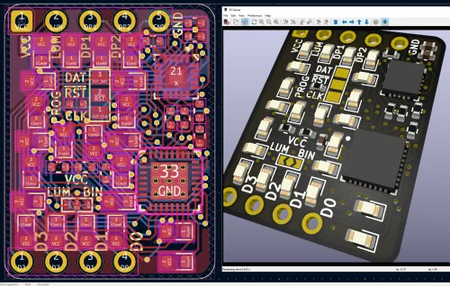
Figure 1
: Improved third version of the board, the first fabricated prototype! Rendered in KiCad (image by me).PCB Design
I designed the schematic and PCB in KiCad. The first version of the board I designed placed the LED driver in the center of the lower figure-8 and the microcontroller off to the side. There was also a pad to short LUM (the luminance pin) to VCC (thus pegging the display to full brightness) and three programming pads. The decimal point had an independent lower LED, which can be used as an alternate position for the decimal point—or, with both LEDs enabled, to suggest a comma digit separator.
The second version of the board, I improved some spacing and added a few resistors to make programming easier. I also made it so you can short VCC to a pad BIN, which changes the brightness mode of LUM from analog brightness to just boolean on/off.
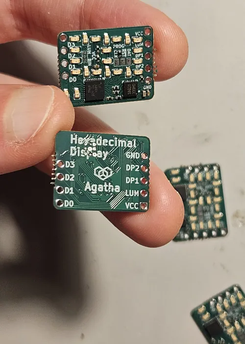
Figure 2
: The first fabricated prototypes![1] (Image by me.)Unfortunately, in the final checks before fabrication, I realized that I had used absolutely tiny LEDs, which would have made fabrication significantly more expensive. I had intended to use cheap 0603 LEDs, but I used my own KiCad footprint based on "D_0201_0603Metric", which came up when I typed "0603" but turns out to be a 0201 package instead. The actual 0603 package is far too large to work with this layout.
Therefore, in the third version (Figure 1), I had to change the layout completely. The driver had to be moved outside the ring of LEDs, meaning the board had to be 0.1" wider. However, I was able to space the LEDs out more, making the displayed character larger, making for actually an overall win. I also made the data pins big-endian, which helped routing and I think is more intuitive anyway.
Finally, I improved the board a bit more (Figure 1), moving some parts inward to accommodate panelization fabrication needs[2]. This is the version I sent to be fabricated—my first PCB fab + assembly ever (Figure 2)! I used a green soldermask, which was cheapest for thinner boards. I selected a thinner board, in turn, to make separating mouse-bites panelization better[3] (I used mouse-bites instead of V-cuts because there's again a price).
Programming Microcontrollers
Programming microcontrollers requires a "programmer": a separate board that talks to the microcontroller. For the N76E003, I got the Nu-Link Pro which (despite the lack of clarity) is indeed compatible with the N76E003. As above, I designed my display so that it would support "in-circuit programming" ("ICP") by exposing the relevant pins as test pads. I soldered together an unexpectedly fiddly flying needle probe thing[4] to connect the programmer, and was able to easily connect the programmer up to it with a quick breadboard build and the NuMicro ICP Programming Tool (from here).
Unfortunately, microcontroller programming is apparently stuck in the precambrian.
As a C++ enjoyer, I'm used to development tools needlessly suffering from usability problems and outright UI bugs, but MCU development is in a whole alternate reality of suckiness.
First, unless you're talking about something like an actual ARM chip, you can forget about Clang (and GCC and MSVC). You can also forget about C++, let alone anything high-level.
For free IDEs, Nuvoton offers something called NuEclipse. I didn't know what this is because the download demands you to log in with your free account, and I couldn't register for a free account because the email activation thing never arrived[5]. That leaves non-free stuff, the most mature of which seemed to be Keil.
I was deeply annoyed by that, because in software development, we expect free tools. Even for the money-grubbing profiteers, the FOSS revolution has been a wild success. The quality of free tools like GCC led to MSVC becoming free, and later the creation of VSCode. The open-source nature and expertise sharing built Clang. Researchers sharing algorithms, pull-requests from random strangers, bazaar-model bug reports, all are now sacred tradition in software development. And with these changes, everyone got more productive, while the dot-com-era proprietary walled-garden tools failed from a comparative productivity standpoint.
Searching desperately for something my pride would let me use, I was hoping VSCode would have an extension or something. Well, VSCode has nothing for Nuvoton and nothing obvious for 8051 microcontrollers, but I eventually found the thoroughly Chinese Embedded IDE (EIDE) extension, which supports the SDCC compiler, apparently the FOSSy standard, and works well-enough.
It was also not obvious how to get platform code for the N76E003, but eventually I surmised it's N76E003_BSP[6]. The code doesn't even build, and I had to fix it in a few places to get it to compile. But, I was able to write my driver code (which was trivial compared to grappling with all this nonsense). Then, using the NuMicro ICP Programming Tool, I could flash the hex code to the actual device!
After which the LEDs did not light up.
Debugging with the Keil Dumpsterfire
In computer graphics, this is the equivalent of a black screen. Black screens (zero everywhere) can mean anything, and therefore are so reviled we usually clear the screen to at least gray[7]. I had anticipated this scenario, and before the boards had even arrived I had written drivers that turn the LEDs on unconditionally using the simplest method possible. I also tried my benchtop power supply in case it wanted more amps than then programmer could give. None of this worked either.
EIDE doesn't support debugging, so I bit the bullet and tried Keil μVision. There's a free version for non-commercial use. After lots of installing and uninstalling, messing with bronze-age GUIs from both ARM and Nuvoton, failing to find the N76E003 and relevant compilers, installing an extension that screwed up VSCode globally, and receiving spam bounce messages of my personal information being sent to random 3rd-parties[8], I figured out that I needed to install "C51".
C51 is apparently their buggy ANSI C compiler. It doesn't support mixed-case, standard keywords like inline, directives the N76E003 uses in some places in N76E003_BSP, which I had to edit further to get working, or even ubiquitous compiler headers like <stdbool.h>. There is no value in requiring an obsolete language standard, and of course even less in doing it wrong. Seriously, if they had just made a backend for Clang, we could all have been coding in Go or whatever.
I finally got it sortof compiling. The simulator-debugger apparently assumes all code lines are in ".c" files so, in particular, functions in headers will make the GUI show the little 'currently debugging' arrow next to whatever the line number happens to be in "main.c", even though the actual line of code is literally in a different file.
The simulated N76E003 entered an infinite reset loop, because the linker had apparently decided not to make linking to undefined functions an error, and therefore it was trying to run garbage. The issue was I hadn't sufficiently convinced it that N76E003_BSP exists. Compiling it in put me at about 3.5 kiB of code, which didn't meaningfully reduce even when I specified optimizing for size, and even when I started manually cutting out entire files. (By the by, SDCC compiled my original code to 1765 bytes with no size optimization.)
This was a bit of a problem because it turned out that the Keil I was using was not the free version after all, but a commercial crippleware version only supporting 2 kiB of code. The free version only supports ARM, while the C51 version is distinct and also four major versions of the IDE behind for some reason.
They want $1999 / year for this trash.
Debugging With NuEclipse
Uninstalling Keil, I retried downloading NuEclipse. This time, I got the email, registered, and installed it, cheerfully ignoring its request to be installed on my root drive, as there is only a minuscule amount of free space on it. It cheerfully ignored me right back, at least partially, splitting the install over two drives and my increasingly frayed sanity.
NuEclipse turns out to be a fork of Eclipse, three years out-of-date. I chose SDCC, hoping to keep a good thing going, and it gave me GCC instead, which I guess is also fine. N76E003 is explicitly supported. But no matter what I tried, I couldn't get anything to build, let alone debug[9]. So I had to give up on this too.
Puppetry With Python
Although by this point I could load binaries onto the microcontroller well enough, the process was slow enough to make further experimentation tedious, and of course debugging was still impossible.
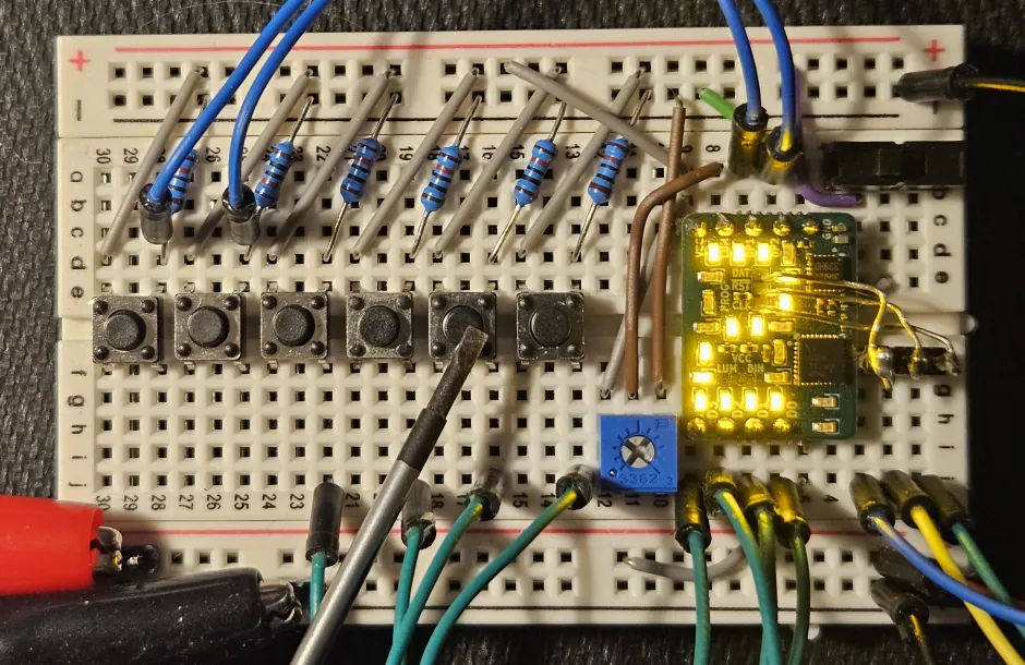
Figure 3
: Testing a prototype hex display on a breadboard. The switch for bit 1 (i.e. value 2) is being pressed with a screwdriver, and the display correctly shows '2'.However, somewhere along the way, I got a devious idea: there is an I2C bus between the N76E003 MCU and LP5024 LED driver, for the former to control the latter. I2C requires pullup resistors, which I had dutifully included. These resistors have a tiny (but exposed!) bit of metal for their ends. What if I connected wires there and tried programming the LP5024 using a more convenient method?
I very carefully placed leads onto the resistors[10] and connected them to my one true love, a Raspberry Pi Pico. The Pico supports MicroPython, which interactively connects to the host computer via USB. This done, I was able to send I2C commands to the LP5024, and figure out what I was doing wrong.
The problem turned out to be simply that I hadn't understood the LED driver chip's state machine quite right, and so the issue was fairly easy to fix. After that, I was able to quickly fix my entire firmware and get the N76E003 to do the job! It turns out my code was fine except for this misunderstanding, and in particular the vital 4-to-13 table for LED mapping was dead perfect on the first go.
Of course, this doesn't really count as proper debugging, but what can you expect from the precambrian?
In the final section, I'll improve the design, developing the Six-Teeny display!
Back to Six-Teeny Intro or Electronics Projects.