CS 6620.001 "Ray Tracing for Graphics" Fall 2014
Welcome to my ray tracing site for the course CS 6620.001, being taught at the University of Utah in Fall 2014 by Cem Yuksel.
Welcome fellow students! I have lots of experience tracing rays, and with graphics in general, and so I'll be pleased to help by giving constructive tips throughout (and I'll also try very hard to get the correct image, or say why particular images are correct as opposed to others). If you shoot me an email with a link to your project, I'm pretty good at guessing what the issues in raytracers are from looking at wrong images.
Hardware specifications, see bottom of page.
Timing information will look like "(#t #s ##:##:##)" and corresponds to the number of threads used, the number of samples (per pixel, per light, possibly explained in context), and the timing information rounded to the nearest second.
Project 1 - "Ray Casting"
I am choosing to use my own code entirely. This is mainly because my graphics codebase is tremendously extensive. As a note to graders/TAs/other-people-with-access-to-the-source, I will try to provide all of the code needed for the code to run, and while it is quite organized, I might leave something out.
I used tinyxml2 instead of tinyxml, which is cleaner in my opinion. It's a bit tricky to get find resources on how to use it, but it's pretty foolproof.
I had some trouble getting the matrix order to match what the file was expecting. In particular, the way the nested transformations is done is a bit awkward. For debugging, I recommend only drawing "sphere1" and "sphere2" and then work on adding "sphere3" later. One incorrect way to do the transformations is to switch the order you do the transformations for one hierarchy level versus another. If you've got it backwards for this file, you might get this (16t 100s 00:01:21):

Here's a Python (with PyGame and PyOpenGL) script to help you visualize the scene and try out different transformation matrices: "prj1_draw.py". Press "v" to toggle whether you're in flyaround mode (where you can move around the scene with a simple camera) or in the render mode (GL view of what your raytracer should make).
If you just want the short version, the correct (final, world space) matrices to use are:
- "sphere1":\[ \begin{bmatrix} 25 & 0 & 0 & 0 \\ 0 & 25 & 0 & 50 \\ 0 & 0 & 25 & -25 \\ 0 & 0 & 0 & 1 \end{bmatrix} \]
- "sphere2":\[ \begin{bmatrix} 5 & 0 & 0 & 0 \\ 0 & 5 & 0 & 50 \\ 0 & 0 & 5 & 5.1 \\ 0 & 0 & 0 & 1 \end{bmatrix} \]
- "sphere3":\[ \begin{bmatrix} 1 & 0 & 0 & 0 \\ 0 & 1 & 0 & 50 \\ 0 & 0 & 1 & 11.1 \\ 0 & 0 & 0 & 1 \end{bmatrix} \]
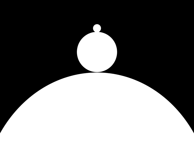
If you do everything right, you should get the following result (maybe with jaggies, since this has 100 random samples per pixel) (16t 100s 00:01:16):
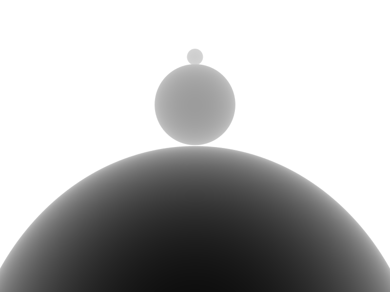
Here's the depth image, with a minimum depth of 30 and a maximum depth of 55 (16t 100s 00:01:17):
Proceed to the Next Project.
Hardware
Except as mentioned, renders are done on my laptop, which has:
- Intel i7-990X (12M Cache, [3.4{6|7},3.73 GHz], 6 cores, 12 threads)
- 12 GB RAM (DDR3 1333MHz Triple Channel)
- NVIDIA GeForce GTX 580M
- 750GB HDD (7200RPM, Serial-ATA II 300, 16MB Cache)
- Windows 7 x86-64 Professional (although all code compiles/runs on Linux)